Project Context
Modern aircraft rely on automated flight control systems to maintain stability, track commanded states, and reject atmospheric disturbances — tasks too fast and too precise for a pilot to perform manually at all flight conditions. The PID controller is the foundational architecture behind elevator deflection systems, autothrottle, and autopilot modes on virtually every commercial aircraft flying today. This project applied that theory to the McDonnell Douglas DC-8: a classic long-range jet airliner whose well-documented stability derivatives made it an ideal subject for a full modal analysis and controller synthesis workflow.
- Extract short period, phugoid, and Dutch roll transfer functions from DC-8 stability derivatives at sea level standard (Mach 0.218, V = 243 ft/s)
- Compute natural frequencies and damping ratios for all three longitudinal and lateral-directional flight modes
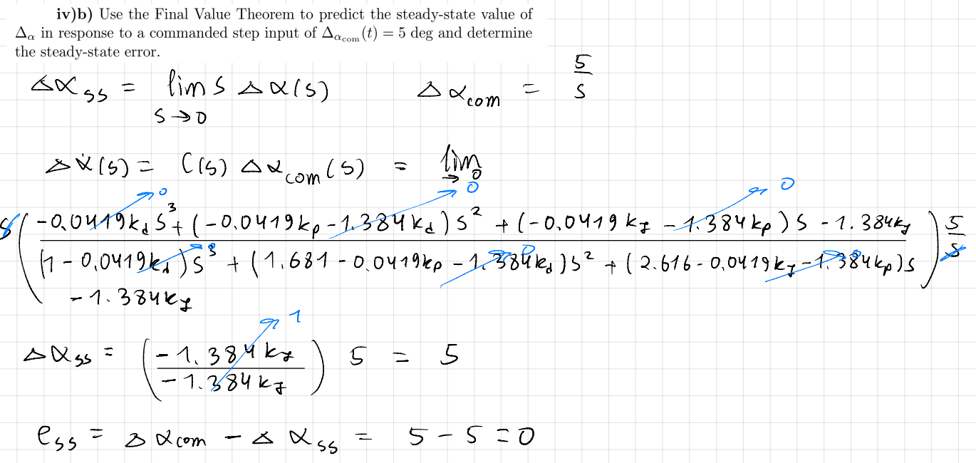
- Design an elevator-input PID controller to regulate angle of attack (Δα) to a 5° step command with Mp ≤ 5% and ts < 10 s
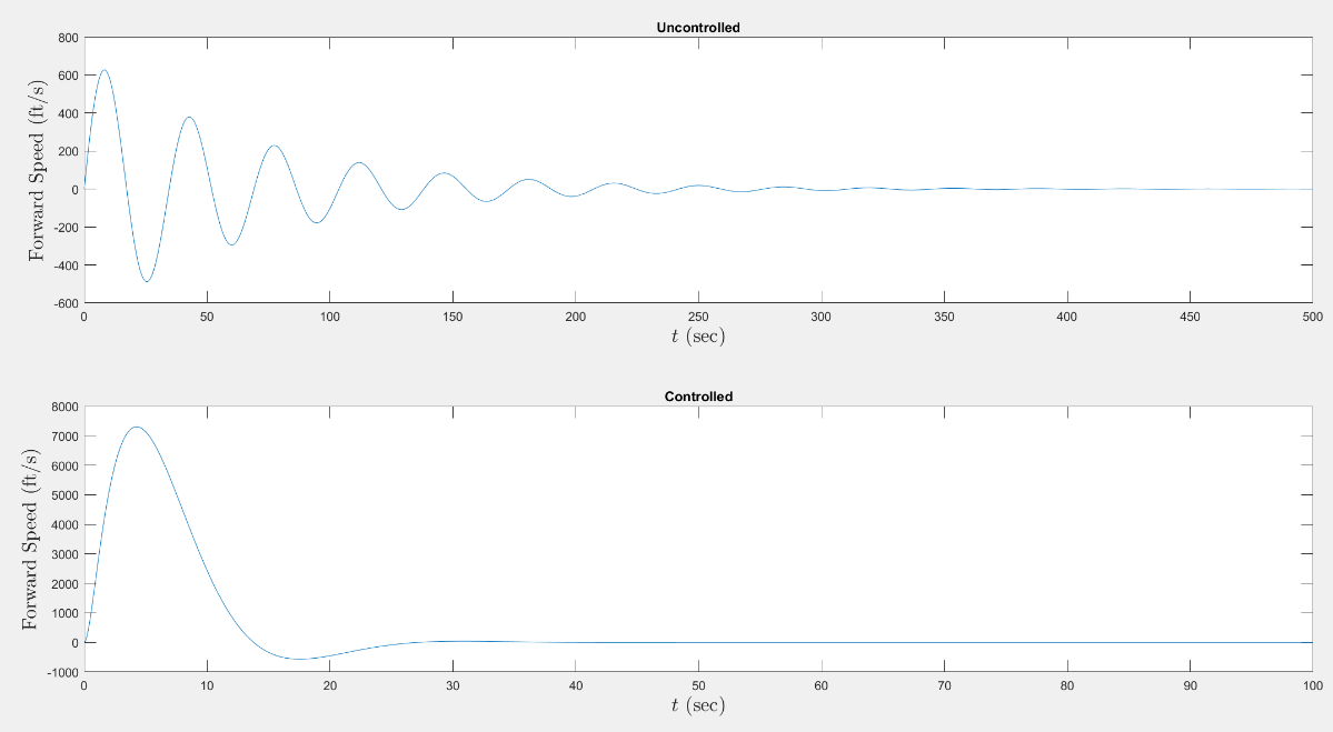
- Design a throttle-input PID controller to regulate forward speed (ΔU) with Mp ≤ 7% and ts < 15 s
- Verify steady-state tracking analytically with the Final Value Theorem for both control loops